Understanding Pressure Balanced Expansion Joints

A formula free explanation
To explain a pressure balanced expansion joint, many an engineer will eagerly pencil out off-setting load vectors – also called the beloved free-body diagram. We engineers live and die by free-body diagrams. All the most important questions in life can be explained by free-body diagrams. As much as I’d love to indulge that psychosis… that’s for another day.
Visualizing the load
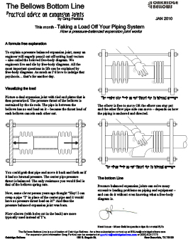
Picture a dual expansion joint with tied end plates that is then pressurized. The pressure thrust of the bellows is restrained by the tie rods. The pipe in between the bellows has no end load on it – because the thrust load of each bellows cancels each other out.
You could grab that pipe and move it back and forth as if it had no internal pressure. The center pipe pressure thrust is balanced. The only resistance you would feel is that of the bellows spring rate.
Now, some clever person years ago thought “Hey! I can swap a pipe ‘T’ in place of the center pipe and it would have no pressure thrust load on it!” And thus the pressure balanced expansion joint was born.
Flow elbows (with holes cut in the back) are more typically used instead of T’s.
The center pipe feels no end-thrust due to internal pressure
The elbow is free to move OR the elbow can stay put and the other flow pipe side can move – depends on how the piping is anchored and directed.
The elbow feels no end-thrust due to internal pressure
The bottom Line
Pressure balanced expansion joints can solve many excessive loading problems on piping and equipment – and can do it without even knowing what a free-body diagram is.


